Amorphous Metal Core Oil-immersed Transformers
05-22 2025 | By:
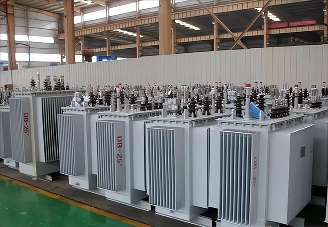
Amorphous Metal Core Oil-immersed Transformers
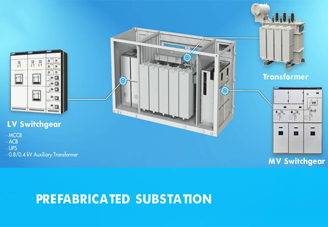
1.Summary
Amorphous alloy transformer is a green new energy saving transformer with amorphous alloy strip of core material. Compared to S11 transformer, it’s open circle losses reduce about 70%. And it is an energy saving product.
The Oil-immersed distribution amorphous alloy transformer meet the standard of IEC60076、GB1094、GB/T25446 and obtain the type test report of National transformer Quality supervision and Inspection Center. It’s an energy-saving product, passing PCCC energy-saving certificate.
2.Standards
IEC60076、GB1094、GB/T25446、GB20052
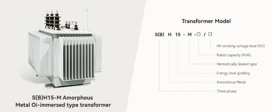
Amorphous Metal Replacing Silicone Steel
Amorphous metal is a metallic material with a disordered atomic-scale structure.
Amorphous metal is non-crystalline, the alloys of boron, silicon, phosphorus, and other glassformers with magnetic metals (iron, cobalt, nickel) are magnetic, with low coercivity and high electrical resistance. The high resistance leads to low losses by eddy currents when subjected to alternating magnetic fields, a property useful e.g. transformer magnetic cores.
1) All raw materials are supplied by Hitachi Metals with iron loss of less than 70-80% of the standard silicon steel.
2) The company has special treatment, procedure, and manufacturer processes, which have patent numbers: 200810238258.6,20082015857.5,200820215858.X, 200820215812.8, 200820215814.7.
3) The core structure is clean and strong, which is not influenced by the movement created during transportation.
4) The three-column structure can withstand high-level harmonics. At Y-connection, the transformer can resist the 3rd harmonic in the network.
Technical specification of amorphous alloy oil-immersed distribution transformer
| S(B)H15-M Amorphous Metal Core Oil-immersed transformer | |||||||||
| Capacity (KVA) |
Voltage Ratio | Vector Group | LWA | No Load Loss (W) |
Load Loss At 75℃ (W) |
No Load Current (%) | Impedance 75℃ (%) | ||
| High Voltage (KV) |
HV Tapping % |
Low Voltage (KV) |
|||||||
| 100 |
6.0 6.3 10 10.5 |
±2*2.5% |
0.4 |
Dyn11 |
52 | 75 | 1500 | 1 |
4 |
| 125 | 54 | 85 | 1800 | 0.9 | |||||
| 160 | 100 | 2200 | 0.7 | ||||||
| 200 | 56 | 120 | 2600 | 0.7 | |||||
| 250 | 140 | 3050 | 0.7 | ||||||
| 315 | 58 | 170 | 3650 | 0.7 | |||||
| 400 | 200 | 4300 | 0.5 | ||||||
| 500 | 60 | 240 | 5150 | 0.5 | |||||
| 630 | 320 | 6200 | 0.3 |
4.5 |
|||||
| 800 | 62 | 380 | 7500 | 0.3 | |||||
| 1000 | 450 | 10300 | 0.3 | ||||||
| 1250 | 65 | 530 | 12000 | 0.2 | |||||
| 1600 | 630 | 14500 | 0.2 | ||||||
| 2000 | 67 | 750 | 17400 | 0.2 |
5 |
||||
| 2500 | 900 | 20200 | 0.2 | ||||||
You may also find these interesting: