SCBH15-100~2500-10 Amorphous alloy dry-type transformer
07-02 2025 | By:
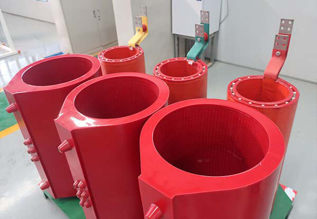
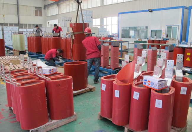
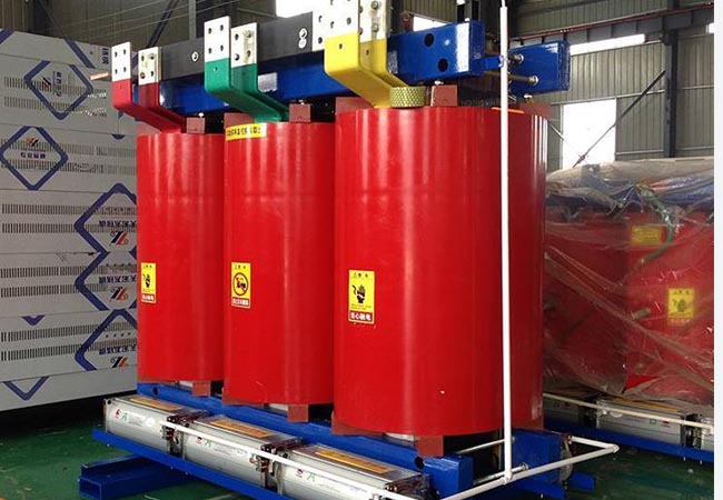
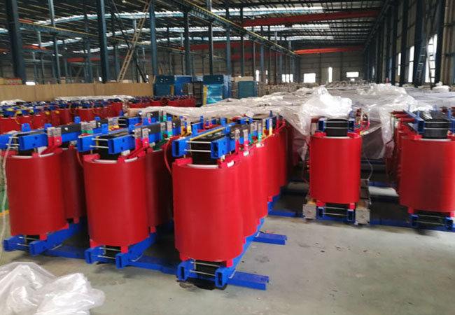
SCBH15-100~2500-10 Amorphous alloy dry-type transformer is a new energy-saving power distribution equipment with the advantages of low no-load loss, oil-free, flame retardant and self-extinguishing, moisture-resistant and crack-resistant. It can replace ordinary dry-type transformers and is mainly suitable for power distribution industries such as rural power grids and urban power grids; commercial buildings, high-rise buildings, airports, industrial and mining enterprises, power plants, oil platforms, subways and tunnels and other important places with fire protection requirements can also be combined with switch cabinets to form box-type substations.
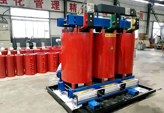
SCBH15-100~2500-10 Amorphous alloy dry-type transformer
Implementation standards
GB1094.11-2007 Power transformers
GB/T22072-2008 Technical parameters and requirements for dry-type amorphous alloy core distribution transformers
JB/T3837-2010 Transformer product model compilation method
International standard IEC726
SCBH15-100~2500-10 Amorphous alloy dry-type transformer
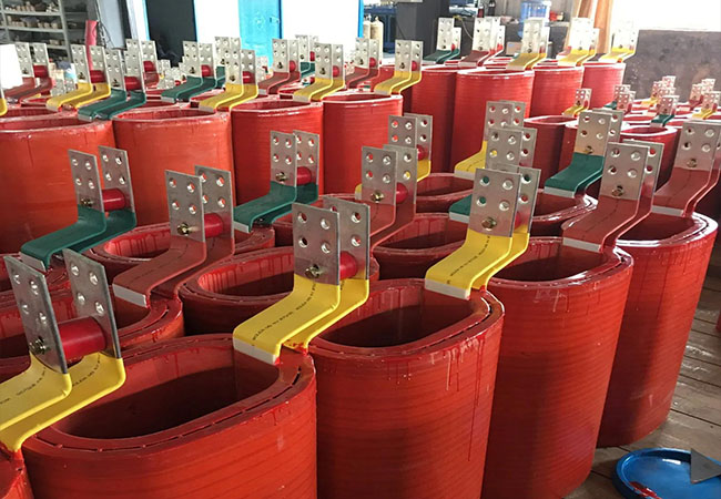
Structural features
1. Small size and light weight;
2. Safe, reliable, pollution-free, can be directly operated at the load center;
3. High mechanical strength, strong short-circuit resistance, small partial discharge, good thermal stability, high reliability and long service life;
4. Small no-load loss, high efficiency, low noise, and obvious energy-saving effect;
5. Good heat dissipation performance, strong operating capacity, and can increase capacity operation when forced air cooling;
6. Good moisture-proof performance, suitable for operation in high humidity and other harsh environments:
7. It has the characteristics of environmental protection, flame retardant, explosion-proof, maintenance-free, etc.; mainly suitable for power distribution industries such as rural power grid and urban power grid; commercial buildings, high-rise buildings, airports, industrial and mining power plants, oil platforms
Important places such as subways and tunnels with special fire protection requirements can also be combined with switch cabinets to form box-type substations.
SC(B)H15-M series amorphous alloy dry-type transformer
| Type | Boundarydimension(mm) | |||||
| a | b | C | d | h | j | |
| SC10-30/20(10) | 770 | 650 | 500 | 500 | 890 | 265 |
| SC10-50/20(10) | 790 | 650 | 500 | 500 | 990 | 275 |
| SC10-80/20(10) | 830 | 650 | 500 | 500 | 1050 | 285 |
| SC10-100/20(10) | 890 | 650 | 500 | 500 | 1100 | 300 |
| SC10-160/20(10) | 1350 | 650 | 500 | 500 | 1250 | 325 |
| SC10-200/20(10) | 1350 | 650 | 500 | 500 | 1250 | 325 |
| SCB10-250/20(10) | 1500 | 800 | 680 | 700 | 1400 | 510 |
| SCB10-315/20(10) | 1520 | 800 | 680 | 700 | 1460 | 520 |
| SCB10-400/20(10) | 1540 | 800 | 680 | 700 | 1510 | 520 |
| SCB10-500/20(10) | 1550 | 1050 | 800 | 800 | 150 | 520 |
| SCB10-630/20(10) | 1560 | 1050 | 800 | 800 | 1580 | 520 |
| SCB10-800/20(10) | 1620 | 1050 | 800 | 800 | 1650 | 545 |
| SCB10-1000/20(10) | 1680 | 1050 | 800 | 800 | 1700 | 570 |
| SCB10-1250/20(10) | 1750 | 1050 | 800 | 800 | 1850 | 620 |
| SCB10-1600/20(10) | 2200 | 1300 | 1050 | 1050 | 2150 | 750 |
| SCB10-2000/20(10) | 2300 | 1300 | 1050 | 1050 | 2250 | 800 |
| SCB10-2500/20(10) | 2450 | 1300 | 1050 | 1050 | 2300 | 850 |
| Ratedcapacity (kVA) | Voltagegroup | Vector group | Impedance voltage (%) | No-load loss (W) | Loadloss120℃ (W) | No-load current (%) | ||
| HV (kV) | Tap range | LV(kV) | ||||||
| 30 | 20 22 24 | ±2×2.5% | 0.4 | Dyn11 or YynO | 6 | 300 | 1100 | 2.2 |
| 50 | 340 | 1240 | 2.0 | |||||
| 80 | 420 | 1500 | 2.0 | |||||
| 100 | 540 | 2000 | 1.8 | |||||
| 160 | 680 | 2470 | 1.5 | |||||
| 200 | 740 | 2950 | 1.5 | |||||
| 250 | 850 | 3420 | 1.3 | |||||
| 315 | 970 | 4090 | 1.3 | |||||
| 400 | 1150 | 4850 | 1.1 | |||||
| 500 | 1350 | 5800 | 1.1 | |||||
| 630 | 1530 | 6840 | 1.0 | |||||
| 800 | 1760 | 8270 | 1.0 | |||||
| 1000 | 2070 | 9790 | 0.85 | |||||
| 1250 | 2390 | 11540 | 0.85 | |||||
| 1600 | 2790 | 13870 | 0.85 | |||||
| 2000 | 3240 | 16390 | 0.7 | |||||
| 2500 | 3870 | 19380 | 0.7 | |||||
You may also find these interesting: