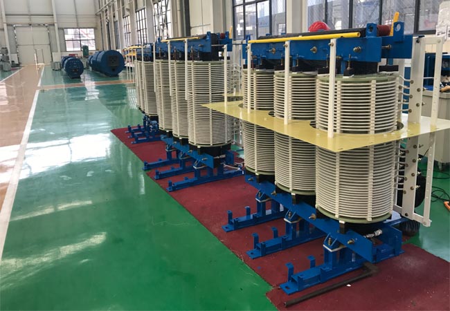
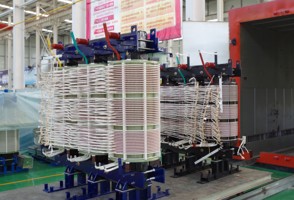
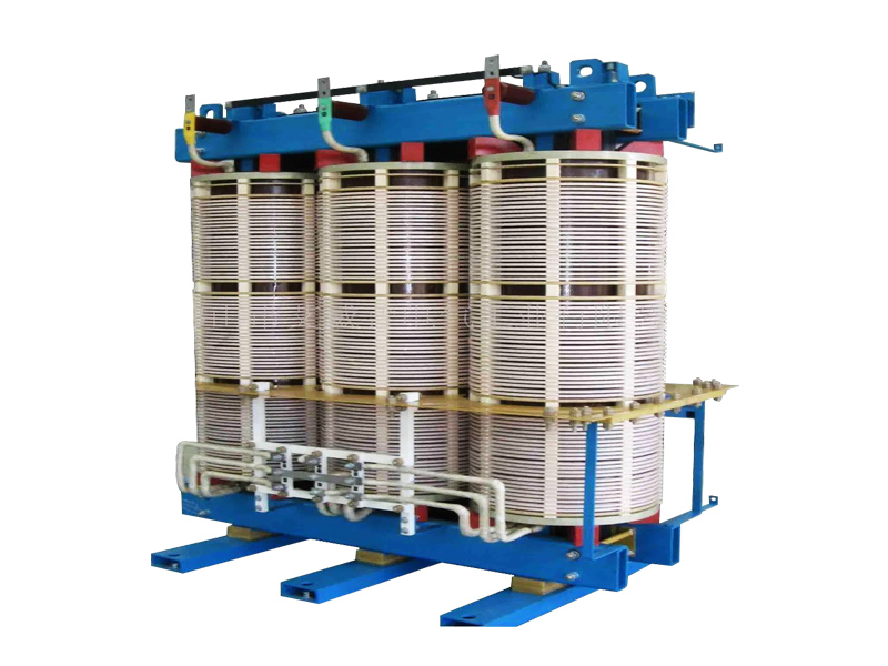
Dry-type phase-shifting rectifier transformer-customized on demand
06-01 2025 | By:
Main uses of phase-shifting rectifier transformer
phase-shifting transformers
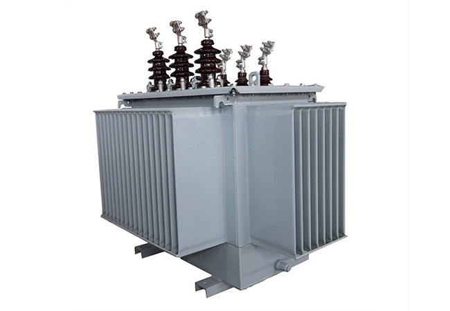
Rectifier transformers are power transformers for rectifier equipment. The characteristic of rectifier equipment is that the primary side inputs AC, and the secondary side outputs DC after passing through the rectifier element. Conversion is a general term for the three working modes of rectification, reverse current and frequency conversion, and rectification is the most widely used one. The transformer used as the power supply of the rectifier device is called a rectifier transformer. Most of the rectifier DC power supplies used in industry are obtained from the AC power grid through rectifier transformers and rectifier equipment.
Electrochemical industry
This is the industry with the most rectifier transformers. Non-ferrous metal compounds are electrolyzed to produce aluminum, magnesium, copper and other metals; salt is electrolyzed to produce chlorine alkali; water is electrolyzed to produce hydrogen and oxygen.
DC power supply for traction
DC power grid used for mines or urban electric locomotives. Because the valve side is connected to the overhead line, there are many short-circuit faults, the DC load variation amplitude is large, and the electric locomotive is often started, resulting in short-term overloads of varying degrees. For this reason, the temperature rise limit and current density of this type of transformer are both low. The impedance is about 30% larger than the corresponding power transformer. DC power supply for transmission
It is mainly used to power DC motors in electric transmission, such as the armature and excitation of rolling mills.
The voltage of this type of rectifier transformer for DC transmission is generally above 110kV, and the capacity is tens of thousands of kilovolt-amperes. Special attention should be paid to the AC and DC superposition of ground insulation. In addition, there are DC power supplies for electroplating or electrical processing, DC power supplies for excitation, DC power supplies for charging and electrostatic dust removal, etc.
The phase shifting method of rectifier transformer
The simplest phase shifting method is to use two windings connected by quantity and angle on the secondary side, which can increase the pulse number of the rectifier furnace
For high-power rectifier equipment, more pulse numbers are required, and the number of pulses is 18, 24, 36, etc., which is increasing day by day.
A phase shifting winding is set on the primary side of the rectifier transformer for phase shifting. There are three ways to connect the phase shifting winding with the main winding, namely, by
hexagon and extended triangle.
The voltage regulation range of the rectifier transformer used in the electrochemical industry is much larger than that of the electric furnace transformer. For chemical salt electrolysis, the voltage regulation range is usually 56%–105%, and for aluminum electrolysis, the voltage regulation range is usually 5%–105%. Commonly used methods are variable flux voltage regulation, series transformer voltage regulation and auto-coupling voltage regulator voltage regulation, just like electric furnace transformers. In addition, due to the characteristics of the whole, the phase angle of the silicon rectifier element conduction can be directly controlled on the valve side of the rectifier furnace, and the average value of the whole can be smoothly adjusted. This voltage regulation method is called phase-controlled voltage regulation. To achieve phase-controlled voltage regulation, one method is to use a crystal valve tube, and the other is to use a self-saturated reactor. The self-saturated reactor is basically composed of an iron core and two windings. One is the working winding, which is connected in series between the secondary winding of the transformer and the rectifier, and the load current flows through it; the other is the DC control winding, which is supplied by another DC control current, and its main principle is to use the nonlinear change of ferromagnetic materials to make the reactance value of the working winding vary greatly. By adjusting the DC control current, the phase control angle a can be adjusted, thereby adjusting the average value of the rectified voltage.
Technical parameters of the transformer
Rated power: 50/60 (KVA)
Efficiency (n): 98%
Voltage ratio: 400/220 (V)
Appearance structure: vertical
Cooling method: natural cooling
Moisture-proof method: open
Number of windings: double windings
Core structure: core type
Cooling form: dry type
Core shape: U type
Number of power phases: single phase
Frequency characteristics: low frequency
Model: ZDG-30/0.4
Application range: rectifier
Dry-type phase-shifting rectifier transformer Performance Parameters
| Type | Ratedcapacity(kVA) | Qtyof secwindings | Shortcircuit impedance(%) | Dimension (L×WxH,mm) | Totalweight(kg) |
| ZT(P)SFG(H)-250/6 | 250 | 9 12 15 18 21 | 6-9% | 1300×880×1440 | 970 |
| ZT(P)SFG(H)-315/6 | 315 | 1300×880×1440 | 1110 | ||
| ZT(P)SFG(H)-400/6 | 400 | 1360×880×1450 | 1200 | ||
| ZT(P)SFG(H)-500/6 | 500 | 1360×960×1490 | 1380 | ||
| ZT(P)SFG(H)-630/6 | 630 | 1360×960×1500 | 1530 | ||
| ZT(P)SFG(H)-710/6 | 710 | 1440×960×1500 | 1680 | ||
| ZT(P)SFG(H)-800/6 | 800 | 1480×960×1520 | 1790 | ||
| ZT(P)SFG(H)-900/6 | 900 | 1480×960×1540 | 1940 | ||
| ZT(P)SFG(H)-1000/6 | 1000 | 1500×960×1550 | 2110 | ||
| ZT(P)SFG(H)-1120/6 | 1120 | 1550×960×1580 | 2190 | ||
| ZT(P)SFG(H)-1250/6 | 1250 | 1580×960×1630 | 2440 | ||
| ZT(P)SFG(H)-1400/6 | 1400 | 1610×1020×1630 | 2610 | ||
| ZT(P)SFG(H)-1600/6 | 1600 | 1660×1020×1680 | 2890 | ||
| ZT(P)SFG(H)-1800/6 | 1800 | 1650×1020×1740 | 3060 | ||
| ZT(P)SFG(H)-2000/6 | 2000 | 1680×1020×1800 | 3420 | ||
| ZT(P)SFG(H)-2250/6 | 2250 | 1720×1020×1840 | 3810 | ||
| ZT(P)SFG(H)-2500/6 | 2500 | 1760×1020×1860 | 4120 | ||
| ZT(P)SFG(H)-2800/6 | 2800 | 1800×1020×1860 | 4490 | ||
| ZT(P)SFG(H)-3000/6 | 3000 | 1820×1120×1860 | 4840 | ||
| ZT(P)SFG(H)-3150/6 | 3150 | 1860×1120×1900 | 5200 | ||
| ZT(P)SFG(H)-3500/6 | 3500 | 1900×1120×1940 | 5620 | ||
| ZT(P)SFG(H)-3750/6 | 3750 | 1960×1120×2050 | 5810 | ||
| ZT(P)SFG(H)-4000/6 | 4000 | 1990×1200×2050 | 6210 | ||
| ZT(P)SFG(H)-4500/6 | 4500 | 2070×1200×2100 | 6910 | ||
| ZT(P)SFG(H)-5000/6 | 5000 | 2150×1200×2100 | 7440 | ||
| ZT(P)SFG(H)-6300/6 | 6300 | 2200×1300×2140 | 8860 | ||
| ZT(P)SFG(H)-8000/6 | 8000 | 2200×1300×2200 | 9670 |
| Type | Ratedcapacity(kVA) | Qtyof secwindings | Shortcircuit impedance(% ) | Dimension(LxWxH,mm ) | Total weight(kg) |
| ZT(P)SFG(H)-315/10 | 315 | 15 18 21 24 27 30 36 | 6-9% | 1380×920×1450 | 1090 |
| ZT(P)SFG(H)-400/10 | 400 | 1380×920×1490 | 1250 | ||
| ZT(P)SFG(H)-500/10 | 500 | 1420×960×1520 | 1410 | ||
| ZT(P)SFG(H)-630/10 | 630 | 1450×960×1550 | 1640 | ||
| ZT(P)SFG(H)-710/10 | 710 | 1480×960×1580 | 1780 | ||
| ZT(P)SFG(H)-800/10 | 800 | 1530×960×1620 | 1860 | ||
| ZT(P)SFG(H)-900/10 | 900 | 1580×960×1640 | 2050 | ||
| ZT(P)SFG(H)-1000/10 | 1000 | 1640×960×1660 | 2250 | ||
| ZT(P)SFG(H)-1120/10 | 1120 | 1640×1020×1680 | 2300 | ||
| ZT(P)SFG(H)-1250/10 | 1250 | 1680×1020×1720 | 2470 | ||
| ZT(P)SFG(H)-1400/10 | 1400 | 1700×1020×1760 | 2810 | ||
| ZT(P)SFG(H)-1600/10 | 1600 | 1780x1020x1800 | 3040 | ||
| ZT(P)SFG(H)-1800/10 | 1800 | 1780×1020×1820 | 3360 | ||
| ZT(P)SFG(H)-2000/10 | 2000 | 1780×1020×1860 | 3690 | ||
| ZT(P)SFG(H)-2250/10 | 2250 | 1780×1020×1900 | 4170 | ||
| ZT(P)SFG(H)-2500/10 | 2500 | 1800×1020×1900 | 4410 | ||
| ZT(P)SFG(H)-2800/10 | 2800 | 1840×1120×1950 | 4720 | ||
| ZT(P)SFG(H)-3000/10 | 3000 | 1880×1120×1950 | 5020 | ||
| ZT(P)SFG(H)-3150/10 | 3150 | 1920×1120×2000 | 5400 | ||
| ZT(P)SFG(H)-3500/10 | 3500 | 1980×1120×2050 | 5400 | ||
| ZT(P)SFG(H)-3750/10 | 3750 | 2010×1200×2050 | 5900 | ||
| ZT(P)SFG(H)-4000/10 | 4000 | 2060×1200×2080 | 6360 | ||
| ZT(P)SFG(H)-4500/10 | 4500 | 2120×1200×2100 | 6960 | ||
| ZT(P)SFG(H)-5000/10 | 5000 | 2200×1200×2150 | 7440 | ||
| ZT(P)SFG(H)-6300/10 | 6300 | 2250×1300×2150 | 8950 | ||
| ZT(P)SFG(H)-8000/10 | 8000 | 2250×1350×2250 | 10900 |
You may also find these interesting: