
Copyright © 2022 ZTELEC Yuguang ElectricTechnology(Henan)CO.,Ltd. All rights reserved.
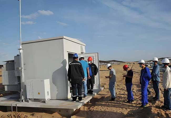
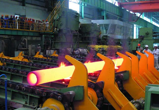
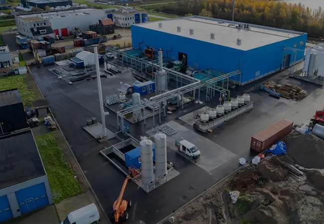
Rectifier Transformer for silicon carbide and graphite electric furnace
| Rated voltage | 6/10/35/110kv |
|---|---|
| Rated capacity | 1000kVA-31.5MVA |
| Application scenarios | Metallurgical Furnace Systems,Silicon Carbide Production.Graphite Electric Furnaces,Industrial Power Retrofit |
| Certifications & Standards | Industrial Power Retrofit |