3 Phase Step up Transformer 400v to 35kv 1/5/10/20 MVA Power Transformer
3 MVA three-phase step-up transformer is engineered to handle 3 million volt-amperes of apparent power, with a primary (input) voltage of 400V (low-voltage, LV) and secondary (output) voltage of 35kV (high-voltage, HV). Its core function is to increase voltage while decreasing current—a critical process for:
- Minimizing power loss during transmission (since losses depend on current, per the formula Ploss=I2R).
- Matching low-voltage power sources (e.g., solar inverters, diesel generators) to 35fkV regional or industrial grids.
Most 3 MVA 400V-to-35kV transformers use an oil-immersed air-cooled (ONAN/ONAF) design:
- Oil Immersion: Submerges windings and core in insulating oil for superior insulation and heat absorption.
- Air Cooling: Relies on natural air flow (ONAN) or supplementary fans (ONAF) for heat dissipation—ideal for areas with limited water access (e.g., rural solar farms).
This design ensures 98.5%+ efficiency, long lifespan (25–30 years), and compliance with global standards (IEC 60076, ANSI C57.12.00).
The 400V input (compatible with most generators/inverters) and 35kV output (a common medium-voltage grid standard) make this transformer versatile for multiple sectors. Below are its most impactful use cases:
Solar inverters typically output 400V (for 1–5 MW units). To connect a 10–20 MW PV plant to the 35kV grid, 3 MVA step-up transformers are the ideal match.
Case Study: 15 MW Solar Farm (Australia)
A developer in Queensland needed to link 15 MW of PV arrays (5×3 MW inverters, each outputting 400V) to the state’s 35kV distribution grid.
Solution: 5 units of 3 MVA 400V-to-35kV transformers.
- Performance: Each transformer handled 3 MW of inverter output, stepping up to 35kV for grid feed-in. ONAF cooling prevented overheating during 40°C summer days.
- Result: 98.7% efficiency, 0 downtime in 18 months, and compliance with Australia’s AS/NZS 61727 solar grid standards.
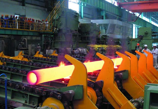
Factories (e.g., cement, textile, food processing) with on-site generators (diesel, gas) often generate 400V power. A 3 MVA step-up transformer lets them:
- Feed excess power into the 35kV grid (to earn feed-in tariffs).
- Use 35kV power for heavy machinery (by stepping down again, if needed).
Example: Textile Mill (India)
A 10,000-spindle mill in Gujarat uses a 3 MW diesel generator (400V output) for backup power. A 3 MVA 400V-to-35kV transformer allows the mill to sell surplus power to India’s 35kV state grid, offsetting 20% of its electricity costs.
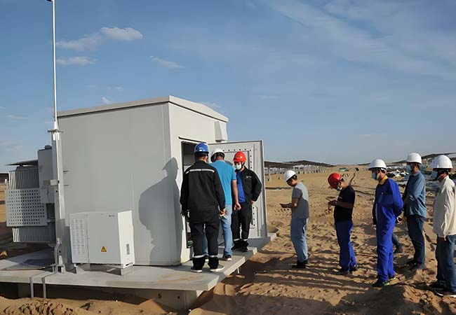
In rural regions, low-voltage (400V) power from local generators (e.g., hydro, wind) needs to be transmitted 10–50 km to villages. Stepping up to 35kV reduces line losses from 15% (at 400V) to 2–3% (at 35kV).
Use Case: Village Electrification (Kenya)
A 5 MW hydro plant in western Kenya generates 400V power. 2 units of 3 MVA 400V-to-35kV transformers transmit power 35 km to 12 villages, ensuring stable electricity for 5,000 households.
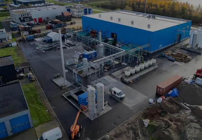
Large data centers often use 400V backup generators. A 3 MVA step-up transformer lets them connect to the 35kV grid for primary power, ensuring uninterrupted operation during outages.
Example: 50,000 sq. ft. Data Center (Germany)
The facility uses a 3 MVA transformer to switch between 400V generator power (backup) and 35kV grid power (primary), achieving 99.99% uptime.
Compared to smaller (1–2 MVA) or larger (5+ MVA) transformers, this model offers unique benefits for medium-scale projects:
3 MVA aligns with the output of common 3 MW inverters/generators—avoiding the inefficiency of “oversizing” (e.g., using a 5 MVA transformer for 3 MW load) or “undersizing” (needing multiple 1 MVA units, which increase installation costs).
By stepping up 400V to 35kV, current is reduced by ~82x (since power P=V×I, so I∝1/V). This cuts line losses from ~10–15% (at 400V) to ~2–3% (at 35kV), saving thousands in energy costs annually.
- Lower Maintenance: Oil-immersed design protects windings from dust/moisture, reducing maintenance frequency (only oil testing every 6 months vs. 3 months for dry-type transformers).
- Long Lifespan: 25–30 years of service (vs. 15–20 years for dry-type models) lowers replacement costs.
- Compact Footprint: 3 MVA units are smaller than 5+ MVA transformers, requiring less site space (critical for urban or space-constrained projects).
35kV is a standard medium-voltage grid voltage in Europe, Asia, Africa, and Australia. This transformer eliminates the need for voltage adapters, ensuring seamless grid integration worldwide.
Below is a standard technical table (values may vary by manufacturer; customizations are available for specific projects):