
Copyright © 2022 ZTELEC Yuguang ElectricTechnology(Henan)CO.,Ltd. All rights reserved.
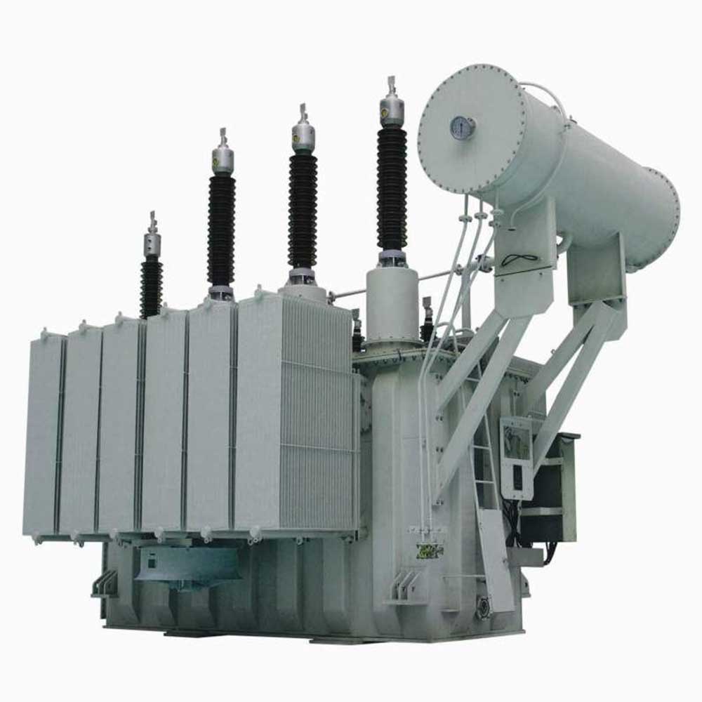
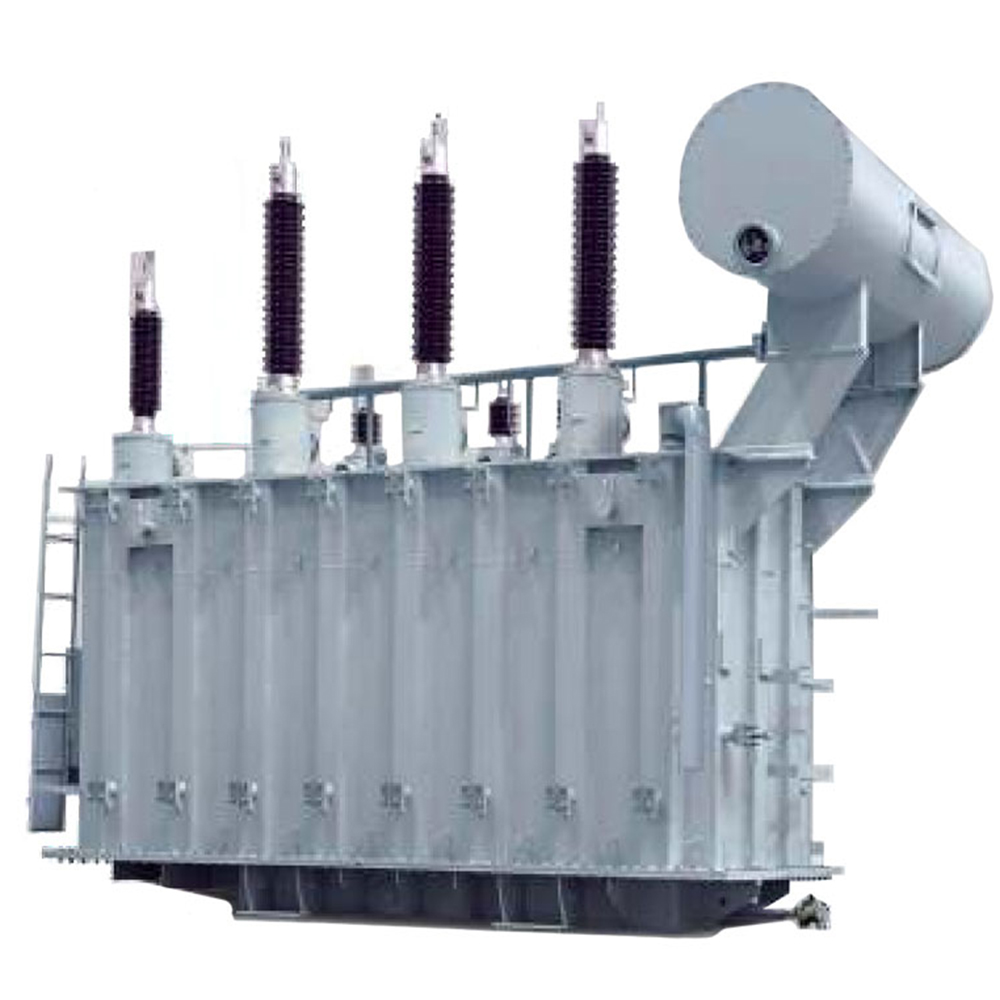
66kV Oil-Immersed Power Transformer
| Rated voltage | 66/110KV |
|---|---|
| Rated capacity | 6300KVA-63MVA |
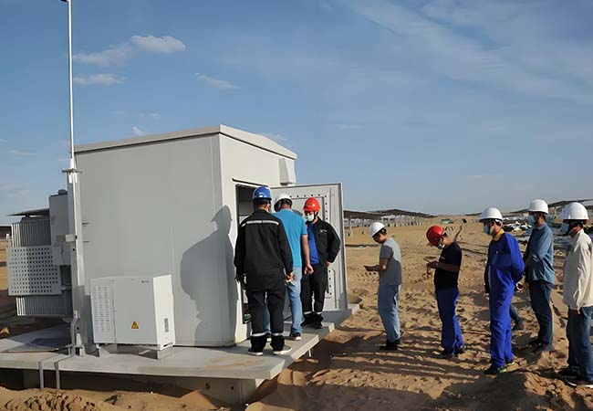
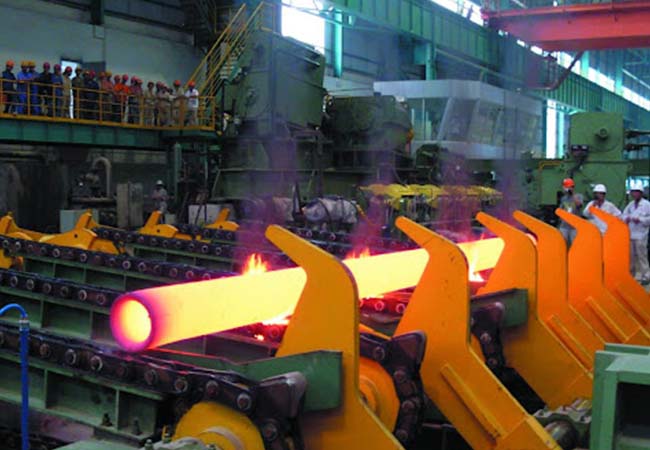
| Application scenarios | Substations, photovoltaic power plants, steel mills, airports, ports, etc. |
| Certifications & Standards | EC、GB、ANSI/IEEE、NEMA |