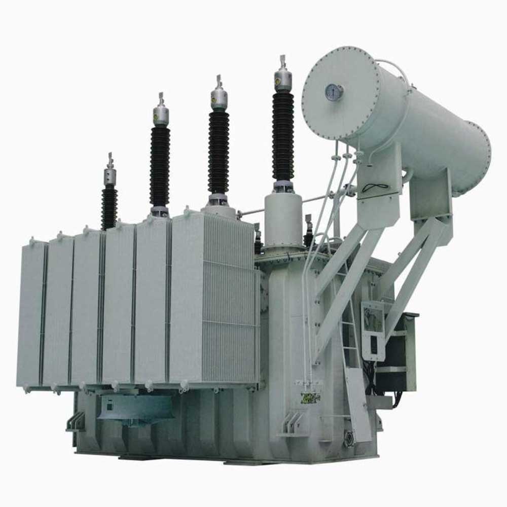
Product Introduction
Our company’s 35kV S11 and SZ11 series products conform to the International Electrotechnical Commission (IEC) 60076. The voltage on the primary side can be manually, electrically, or automatically adjusted within the voltage regulation range using an on-load tap changer to ensure output voltage stability. Transformers of 35kV class and above (16000kVA) adopt a bell-type design, greatly strengthening the mechanical strength of the tank and improving the transformer’s appearance. This product is a next-generation upgrade with significant operational economic benefits.
Product Features
1. Low loss and significant energy saving. In particular, no-load loss is significantly reduced, averaging about 25% lower than the national standard GB/T6451-2008.
2. The core uses high-quality cold-rolled silicon steel sheets, with advanced domestic shearing lines, achieving a burr size of <0.02mm. It features fully oblique joints, no punching, and no overlapping of the yoke. Double-H adhesive bonding between the core columns ensures the three columns and two yokes form a tight, flat, and solid whole, effectively reducing the transformer’s no-load loss, no-load current, and noise.
3. The transformer coils use high-purity oxygen-free copper, effectively reducing copper loss. Coil pads and support bars have rounded corners, resulting in a uniform electric field and increased reliability. Reinforced internal winding support improves stability and prevents instability and deformation. For products with a capacity of 16000KVA or higher, the inner and outer coils are assembled using a unified integral support plate and pressure plate, simultaneously pressing them back to ensure consistent axial coil height and improve the transformer’s resistance to sudden short circuits.
4. Plate clamps and side beams form a robust frame structure. The transformer body and tank are rigidly positioned on six sides, allowing the transformer body to withstand impacts under various transportation conditions without displacement. If the impact during product transportation is less than the specified value, it can be directly put into operation on-site without core lifting inspection, reducing the significant amount of on-site core lifting work.
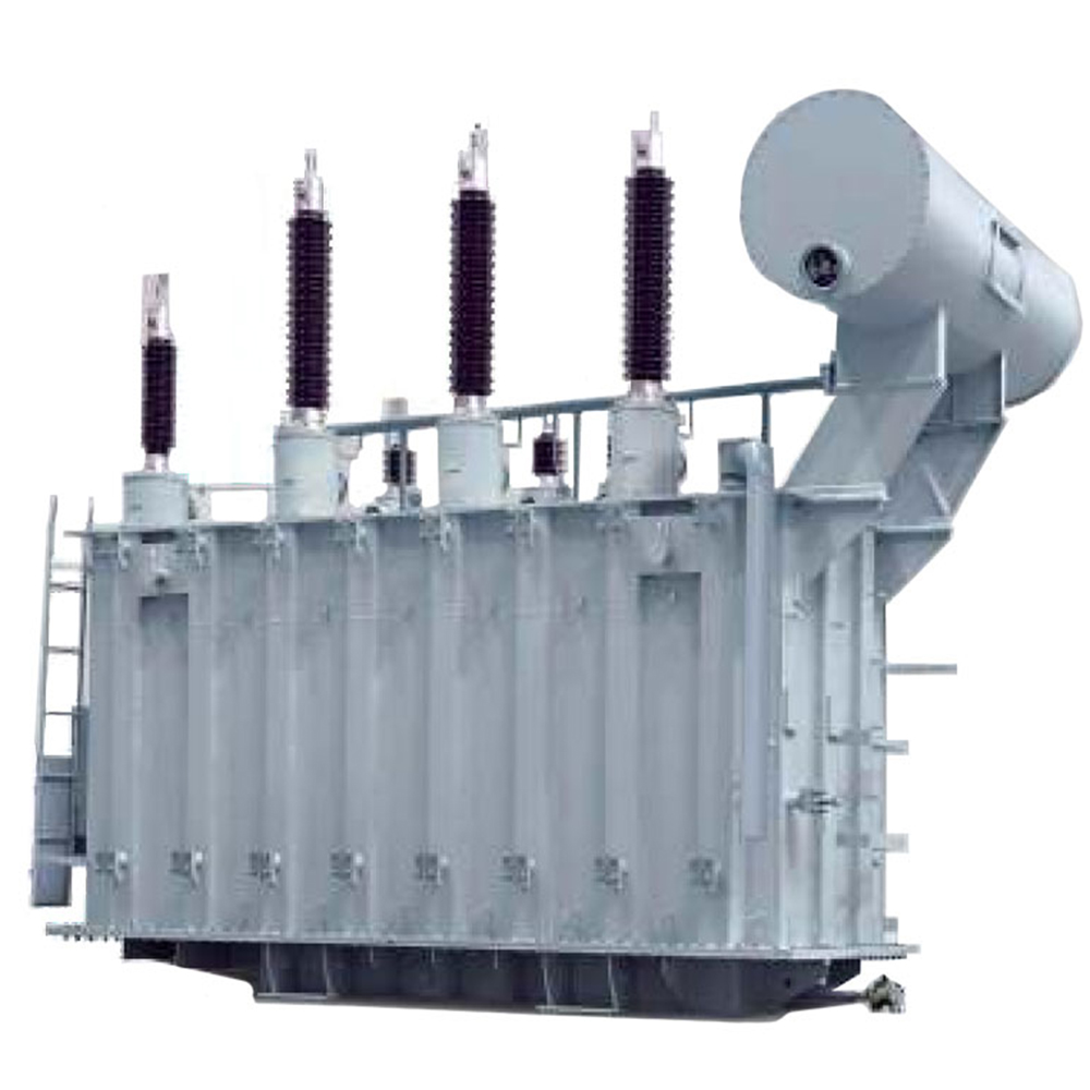
5. The tank wall is made of a single piece of steel plate, folded into a corrugated structure by a large press. This reduces welds, increases mechanical strength, expands the heat dissipation area, and improves heat dissipation. Simultaneously, the corrugated tank wall avoids planar sound wave reflection, thus reducing noise. The transformer has an overall aesthetically pleasing and simple design.
6. The use of a capsule-type oil conservator effectively slows down the aging of transformer oil; the pointer-type oil level gauge avoids false oil level readings and solves the problem of transformer oil aging due to sunlight; the gas relay with a gas collection device facilitates maintenance and operation.
7. For the original traditional sealing structure, especially in areas prone to oil leakage, strict control is implemented from the material procurement stage to ensure that the steel is free from rust, impacts, scratches, and hammering. The tank sealing parts undergo special processing, and the entire tank body is painted to remove sharp burrs and welding slag generated during processing, and to enhance paint adhesion.
Normal Operating Conditions
High Temperature: +40℃
Average Temperature of Hottest Months: +30℃
Average Temperature of Hottest Years: +20℃
Low Temperature: -25℃
Altitude: Not exceeding 1000m
Installation Environment: Free from significant pollution
Outdoor Installation
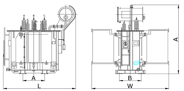
Schematic Diagram of a Non-Excitation Voltage Regulating Power Transformer
35kV S11 Series Off-Circuit-Tap-Changing Power Transformer
| Type |
Raod Capacny
(KVA) |
Voltage comblnation |
Connection
symbol |
NO-load Loss
(kW) |
load Loss
(kW) |
NO-load
Curent
(%) |
Shon-crcuit
Impedance
(%) |
| HV |
Tapping Pange ofH |
LV |
| S11-630/35 |
630 |
35 |
±5 |
3.15
6.3
10.5 |
Yd11 |
0.83 |
7.82 |
1.1 |
6.5 |
| S11-800/35 |
800 |
0.98 |
9.35 |
0.9 |
| S11-1000/35 |
1000 |
1.15 |
11.5 |
0.8 |
| S11-1250/35 |
1250 |
1.41 |
13.9 |
0.7 |
| S11-1600/35 |
1600 |
1.7 |
16.6 |
0.6 |
| S11-2000/35 |
2000 |
2.18 |
18.3 |
0.6 |
| S11-2500/35 |
2500 |
2.56 |
19.5 |
0.6 |
| S11-3150/35 |
3150 |
35-38.5 |
±5 |
3.15
6.3
10.5 |
3.04 |
23 |
0.6 |
7 |
| S11-4000/35 |
4000 |
3.62 |
27.2 |
0.5 |
| S11-5000/35 |
5000 |
4.32 |
31.2 |
0.5 |
| S11-6300/35 |
6300 |
5.25 |
34.9 |
0.4 |
7.5 |
| S11-8000/35 |
8000 |
35~38.5 |
±2×2.5% |
3.15
3.3
6.3
6.6
10.5
11 |
YNd11 |
7.2 |
38.3 |
0.4 |
| S11-10000/35 |
10000 |
8.7 |
45.1 |
0.4 |
| S11-12500/35 |
12500 |
10.08 |
53.6 |
0.4 |
8 |
| S11-16000/35 |
16000 |
12.16 |
65.5 |
0.3 |
| S11-20000/35 |
20000 |
14.4 |
79.1 |
0.3 |
| S11-25000/35 |
25000 |
17.02 |
93.5 |
0.2 |
| S11-31500/35 |
31500 |
20.22 |
112.2 |
0.2 |
|
|
|
|
|
|
|
|
|
|
| Type |
RatedCapachy
(kVA) |
〔kg〕Waight |
(mm)Overall Dimension |
( mm)
Track Spacing |
| OiL |
Total |
(L) |
(W) |
(H) |
| S11-800/35 |
800 |
930 |
3900 |
2300 |
1310 |
2350 |
820×820 |
| S11-1000/35 |
1000 |
1050 |
4550 |
2480 |
1360 |
2450 |
820×820 |
| S11-1250/35 |
1250 |
1200 |
4900 |
2500 |
1420 |
2585 |
820×820 |
| S11-1600/35 |
1600 |
1265 |
5500 |
2650 |
1750 |
2605 |
1070×1070 |
| S11-2000/35 |
2000 |
1365 |
6200 |
2710 |
1850 |
2700 |
1070×1070 |
| S11-2500/35 |
2500 |
1690 |
7200 |
2860 |
2050 |
2800 |
1070×1070 |
| S11-3150/35 |
3150 |
2005 |
9500 |
2950 |
2895 |
2900 |
1070×1275 |
| S11-4000/35 |
4000 |
2145 |
10160 |
3005 |
2900 |
2990 |
1070×1275 |
| S11-5000/35 |
5000 |
2700 |
11600 |
3100 |
3030 |
3140 |
1070×1275 |
| S11-6300/35 |
6300 |
3075 |
13425 |
3250 |
3360 |
3290 |
1070×1275 |
| S11-8000/35 |
8000 |
3475 |
16200 |
3450 |
3475 |
3400 |
1070×1275 |
| S11-10000/35 |
10000 |
4300 |
19000 |
3615 |
3650 |
3550 |
1475×1275 |
| S11-12500/35 |
12500 |
4950 |
21650 |
4000 |
3665 |
3650 |
1475×1475 |
| S11-16000/35 |
16000 |
5875 |
27000 |
4280 |
3900 |
3960 |
1475×1475 |
| S11-20000/35 |
20000 |
6740 |
30450 |
4750 |
4050 |
4100 |
1475×1475 |
| S11-25000/35 |
25000 |
8500 |
34800 |
4875 |
4250 |
4200 |
2040×1475 |
| S11-31500/35 |
31500 |
10000 |
41250 |
5205 |
4625 |
4375 |
2040×1475 |