Traction Transformer for Railway Systems: Design and Technical Requirements
11-05 2026 | By:
1. What Is a Traction Transformer?
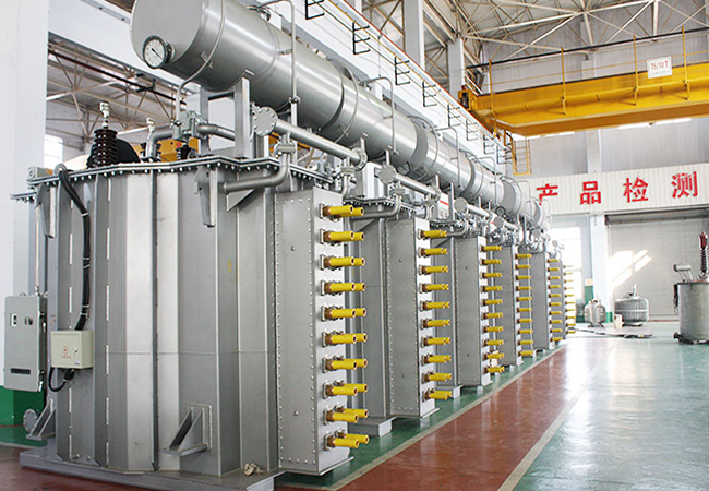
A traction transformer is a specially designed transformer used in railway electrification systems to supply electrical power for train operation. It provides the voltage transformation required by railway traction power networks or onboard electric traction equipment.
Unlike conventional distribution transformers, traction transformers operate under specific railway conditions, including fluctuating loads, frequent power demand changes, electrical disturbances and demanding environmental requirements.
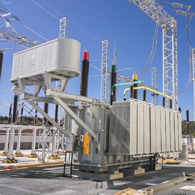
Traction transformers are widely used in:
-
High-speed railway systems.
-
Electrified mainline railways.
-
Urban rail transit and metro systems.
-
Electric locomotives.
-
Light rail and commuter railways.
-
Railway traction substations.
The design of a traction transformer depends on the railway electrification system, installation location, voltage level, load characteristics and applicable railway standards.
For railway infrastructure projects, selecting the correct transformer is essential for maintaining a reliable power supply, supporting train operation and reducing electrical losses.
ZTELEC YUGUANG provides power transformer and special transformer solutions for industrial and infrastructure applications. Railway traction transformer configurations can be evaluated according to project-specific electrical and technical requirements.
2. Main Types of Traction Transformers
Railway traction transformers can be classified according to their installation location and power supply function.
2.1 On-board Traction Transformer
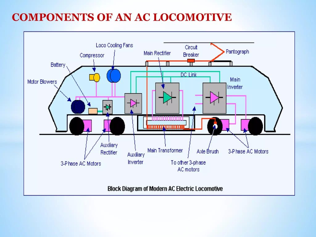
An on-board traction transformer is installed inside an electric locomotive or electric multiple unit (EMU). It receives high-voltage power from the overhead contact line or another railway power supply system and converts it into suitable voltage levels for the train’s traction equipment.
The transformed power is supplied to traction converters, traction motors and auxiliary electrical systems, depending on the train’s electrical architecture.
Key characteristics:
-
Compact and lightweight construction.
-
High power density.
-
Resistance to vibration and mechanical shock.
-
Reliable insulation under railway operating conditions.
-
Efficient thermal management.
-
Compatibility with traction converters and onboard electrical systems.
Typical applications:
-
High-speed electric trains.
-
Electric locomotives.
-
Electric multiple units.
-
Intercity and commuter trains.
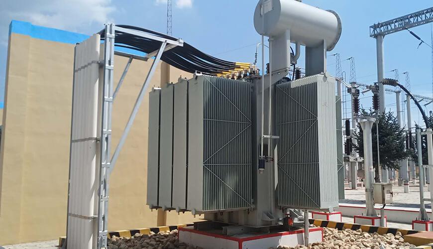
2.2 Traction Substation Transformer
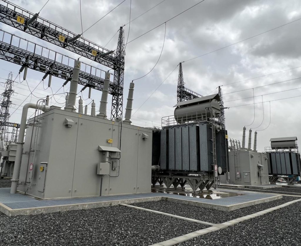
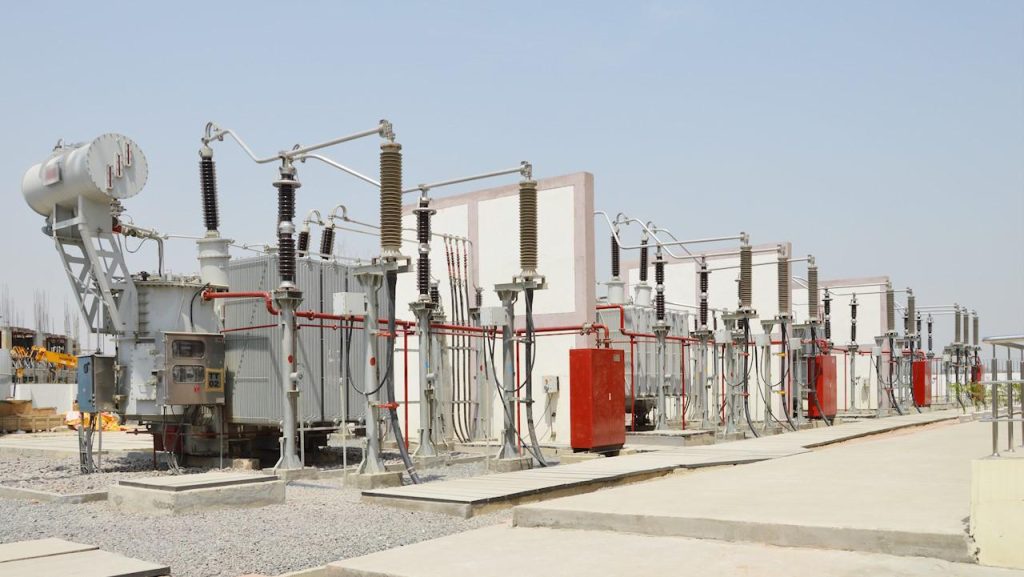
A traction substation transformer is installed in a railway traction substation. It converts power from the utility grid or high-voltage transmission network into the voltage required by the railway traction power supply system.
Its configuration depends on the railway electrification technology.
Common applications include:
-
AC railway traction substations.
-
DC railway traction substations.
-
High-speed railway power supply systems.
-
Metro and urban rail transit power systems.
For example, in a 25 kV AC railway system, the transformer may be used to supply the traction network through the appropriate substation arrangement.
In DC railway systems, transformers may supply rectifier equipment that converts AC power into DC power for the traction network.
2.3 Single-Phase Traction Transformer
Single-phase traction transformers are commonly associated with AC railway electrification systems.
Depending on the railway network, they may be designed for different primary and secondary voltage configurations, including railway-specific winding arrangements.
Important design considerations include:
-
Primary and secondary voltage.
-
Rated capacity.
-
Winding connection and phase arrangement.
-
Impedance and short-circuit performance.
-
Load variation and railway operating cycles.
-
Compatibility with the traction power supply configuration.
2.4 Three-Phase Traction Transformer
Three-phase transformers can be used in railway traction substations and associated railway power distribution systems.
They are designed to transform three-phase grid power into the required output configuration for the railway electrical system.
Depending on the application, the transformer may be connected to rectifier equipment, railway power converters or other traction power supply components.
2.5 Rectifier Transformer for DC Railway Systems
In DC railway systems, a rectifier transformer supplies electrical power to rectifier equipment, which converts AC power into DC power for railway traction.
These transformers are commonly used in metro, tramway and other DC electrified railway systems.
Their design may need to consider:
-
Rectifier circuit configuration.
-
Harmonic currents and additional losses.
-
Phase-shifting requirements.
-
Secondary winding configuration.
-
Thermal performance.
-
Insulation and short-circuit withstand capability.
A rectifier transformer is therefore an important component of a DC railway traction power supply system.
3. Design Features of Railway Traction Transformers
Railway traction transformers must be designed to withstand demanding electrical, thermal and mechanical operating conditions. The design requirements depend on whether the transformer is installed onboard a train or in a stationary traction substation.
3.1 Electrical Design and Load Characteristics
Railway traction loads are not constant. Train acceleration, braking, changes in passenger or cargo loads and operating schedules can cause significant variations in power demand.
The transformer design should consider:
-
Rated power and maximum operating load.
-
Continuous and short-time loading conditions.
-
Load profile and duty cycle.
-
Primary and secondary voltage.
-
Harmonic content and waveform distortion.
-
Short-circuit impedance and system fault conditions.
For onboard traction transformers, the load profile should be developed in coordination with the traction converter and vehicle manufacturer. For traction substation transformers, the railway power supply configuration and network load distribution are essential design inputs.
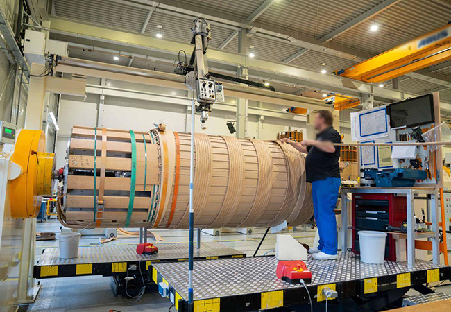
3.2 Core and Winding Design
The transformer core and windings are fundamental to electrical performance, efficiency and operational reliability.
Important considerations include:
-
Low-loss magnetic core materials.
-
Winding conductor selection and current density.
-
Insulation structure and dielectric strength.
-
Mechanical strength under short-circuit forces.
-
Temperature distribution and hot-spot control.
-
Winding arrangement suitable for the required voltage configuration.
For onboard applications, the transformer must also meet strict space and weight limitations. For stationary railway substations, the design may place greater emphasis on capacity, cooling, insulation coordination and outdoor operating conditions.
3.3 Insulation System
The insulation system must withstand operating voltage, transient overvoltage and electrical stress throughout the transformer’s service life.
Depending on the design, traction transformers may use liquid-immersed or dry-type insulation systems.
The insulation design should take into account:
-
Rated voltage and insulation level.
-
Lightning and switching impulse requirements, where applicable.
-
Temperature-rise limits.
-
Partial discharge requirements, where specified.
-
Environmental conditions.
-
Required dielectric tests.
The final insulation arrangement must comply with the applicable railway and transformer standards specified for the project.
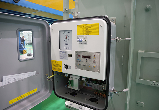
3.4 Cooling System and Temperature Control
Cooling is essential because traction transformers may experience substantial load variations and repeated thermal cycles.
Depending on the installation and design, cooling methods may include:
| Cooling arrangement | Description | Application considerations |
|---|---|---|
| Air natural | Natural air circulation | Suitable for certain dry-type designs |
| Air forced | Fans provide additional cooling | Used where enhanced air cooling is required |
| Oil natural air natural | Natural oil and air circulation | Common for suitable liquid-immersed designs |
| Oil natural air forced | Natural oil circulation with forced-air cooling | Higher cooling requirements |
| Oil forced air forced | Pumped oil and forced-air cooling | Used in selected higher-capacity designs |
For onboard transformers, cooling equipment must be compatible with the available installation space, ventilation arrangement and vehicle operating conditions.
For stationary traction substations, the cooling system should be selected according to rated capacity, ambient temperature, installation environment and maintenance requirements.
3.5 Mechanical Design and Vibration Resistance
Mechanical reliability is especially important for transformers installed on rolling stock.
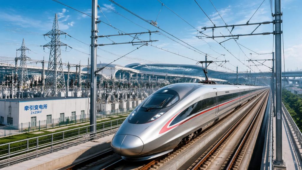
Train operation exposes onboard electrical equipment to vibration, shock and repeated mechanical stress. The transformer structure must be designed to withstand these conditions.
Key design considerations include:
-
Core and winding clamping.
-
Tank and enclosure strength.
-
Secure mounting arrangements.
-
Resistance to vibration and mechanical shock.
-
Protection of terminals and electrical connections.
-
Reliable sealing and protection against environmental contamination.
IEC 61373 addresses shock and vibration testing for equipment used on railway vehicles. IEC 60310:2026 also updates requirements relating to shock and vibration for onboard transformers and inductors.
IEC+1
3.6 Fire Safety and Environmental Protection
Fire protection is an important consideration in railway electrical equipment, particularly for transformers installed inside vehicles or enclosed railway facilities.
The design may need to address:
-
Insulating liquid fire characteristics, where applicable.
-
Fire barriers and enclosure requirements.
-
Smoke and material performance requirements.
-
Oil leakage prevention.
-
Moisture and dust protection.
-
Corrosion resistance.
-
Environmental temperature and altitude.
The specific requirements depend on the railway operator, vehicle design, installation location and applicable fire-safety standards.
4. Technical Specifications of Railway Traction Transformers
The specifications of a railway traction transformer vary according to the railway electrification system and installation location.
A technical specification should clearly distinguish between an onboard transformer and a stationary traction substation transformer.
4.1 Main Technical Parameters
| Parameter | On-board traction transformer | Traction substation transformer |
|---|---|---|
| Installation | Inside locomotive or EMU | Railway traction substation |
| Main function | Supplies traction converters and related onboard circuits | Supplies railway traction power network or conversion equipment |
| Rated capacity | Based on vehicle traction power demand | Based on substation load and railway network requirements |
| Primary voltage | According to overhead line or vehicle supply system | According to utility grid voltage |
| Secondary voltage | According to traction converter configuration | According to AC traction network or rectifier input |
| Frequency | According to railway supply system | According to utility supply system |
| Phase configuration | Vehicle-specific | Single-phase or three-phase, depending on system |
| Cooling | Air-cooled or liquid-cooled, design-dependent | Oil-immersed or dry-type, design-dependent |
| Insulation | Railway vehicle requirements | Substation insulation coordination |
| Mechanical requirements | Vibration and shock resistance | Foundation, enclosure and environmental requirements |
| Protection | Vehicle electrical protection coordination | Substation relay and protection coordination |
| Applicable standards | IEC 60310 and relevant railway standards | Relevant IEC 60076 and railway project standards |
4.2 Typical Railway Electrification Systems
Different railway systems use different traction power supply arrangements. The transformer configuration must match the selected system.
| Railway system | Typical power supply arrangement | Transformer application |
|---|---|---|
| 25 kV AC railway | Single-phase AC overhead supply | Traction substation transformer |
| 2 × 25 kV AC railway | Autotransformer feeding system | Main traction transformer and associated autotransformers |
| 15 kV AC railway | Single-phase AC overhead supply | Railway traction substation transformer |
| 750 V DC metro | AC-to-DC conversion | Rectifier transformer |
| 1,500 V DC railway | AC-to-DC conversion | Rectifier transformer |
| 3,000 V DC railway | AC-to-DC conversion | Rectifier transformer |
Note: These are representative railway electrification arrangements. Actual voltage, frequency, transformer connections and system configuration must be confirmed from the project design.
4.3 Example Technical Specification Format
The following table is an illustrative specification format for a stationary railway traction substation transformer. It is not a fixed ZTELEC YUGUANG product rating.
| Item | Reference specification |
|---|---|
| Product | Railway traction substation transformer |
| Rated capacity | To be determined by load calculation |
| Primary voltage | According to utility grid |
| Secondary voltage | According to railway traction system |
| Frequency | 50 Hz / 60 Hz |
| Number of phases | Project-specific |
| Winding connection | According to traction power supply arrangement |
| Impedance voltage | Project-specific |
| Cooling method | ONAN / ONAF or other specified arrangement |
| Insulation medium | Mineral oil or specified alternative |
| Installation | Indoor / Outdoor |
| Applicable standard | IEC 60076 series and project-specific railway requirements |
For an onboard traction transformer, the specification should additionally include vehicle installation space, weight limitations, vibration and shock requirements, cooling arrangement and traction converter compatibility.
Important: Do not use a generic 25 kV or 750 V figure as the transformer secondary voltage without checking the actual electrical system. The contact-line voltage, rectifier output voltage and transformer winding voltage are different engineering parameters.
5. Applications of Traction Transformers in Railway Systems
5.1 High-Speed Railway
High-speed railway systems require a reliable traction power supply to support high train speeds, frequent operations and large transportation capacity.
Traction transformers are used in railway substations and onboard train systems to provide the electrical energy required for traction operation.
Key requirements include:
-
Stable power supply.
-
High operational reliability.
-
Suitable load capacity.
-
Electrical insulation coordination.
-
Effective thermal management.
-
Compatibility with the railway power supply system.
5.2 Electric Locomotives and EMUs
Electric locomotives and electric multiple units use onboard traction transformers to convert overhead-line power into suitable electrical power for traction converters and auxiliary systems.
The transformer must be engineered around the vehicle’s traction architecture, available space, weight limits and operating profile.
5.3 Metro and Urban Rail Transit
Metro and urban rail transit systems commonly use DC traction power supply arrangements.
In these systems, rectifier transformers work with rectifier units to convert utility AC power into DC power for trains.
Typical applications include:
-
Underground metro systems.
-
Light rail transit.
-
Urban commuter railways.
-
Tramway networks.
5.4 Railway Electrification and Infrastructure Projects
Railway electrification projects require a coordinated power supply network, including traction substations, transformers, switchgear, protection systems and distribution equipment.
Traction transformers are important components in new railway construction, railway electrification upgrades and capacity expansion projects.
6. How to Select the Right Traction Transformer
Selecting a railway traction transformer requires a detailed understanding of the railway power supply system, operating conditions and technical specifications.
The following factors should be considered before purchasing.
6.1 Identify the Installation Type
First, determine whether the project requires an onboard transformer or a stationary traction substation transformer.
| Selection factor | On-board transformer | Substation transformer |
|---|---|---|
| Installation location | Train or locomotive | Railway substation |
| Main priority | Weight, size and vibration resistance | Capacity, voltage transformation and network reliability |
| Load characteristics | Vehicle traction and auxiliary load profile | Railway network load profile |
| Cooling requirements | Vehicle-specific cooling arrangement | Site-specific cooling system |
| Engineering coordination | Train manufacturer and traction converter supplier | Railway power system designer and utility |
These two transformer categories should not be treated as interchangeable.
6.2 Confirm the Railway Power Supply System
The railway electrification system determines the transformer’s voltage configuration, winding arrangement and electrical design.
Before selecting a transformer, confirm:
-
AC or DC railway electrification.
-
Nominal contact-line voltage.
-
Utility grid voltage.
-
System frequency.
-
Single-phase or three-phase configuration.
-
Rectifier or converter arrangement.
-
Grounding and protection requirements.
6.3 Calculate the Required Rated Capacity
Transformer capacity should be determined according to the actual railway load profile.
For onboard applications, consider:
-
Train traction motor power.
-
Number of traction converters.
-
Auxiliary power demand.
-
Acceleration and braking cycles.
-
Continuous and short-time loading.
-
Emergency operating conditions.
For traction substations, consider:
-
Number of trains operating simultaneously.
-
Train headway and operating frequency.
-
Peak traction demand.
-
Regenerative braking arrangements.
-
Future railway capacity expansion.
-
Required redundancy and emergency operating conditions.
6.4 Evaluate Electrical and Thermal Performance
The manufacturer should assess transformer losses, temperature rise, cooling requirements and operating conditions.
For railway projects, additional attention should be paid to harmonic currents, load fluctuations, short-circuit withstand capability and insulation coordination.
6.5 Confirm Railway Standards and Testing Requirements
Standards must be selected according to the transformer installation type.
| Standard | Main application |
|---|---|
| IEC 60310:2026 | Transformers and inductors installed onboard railway rolling stock |
| IEC 60076 series | General power transformer requirements, where applicable |
| IEC 61373 | Shock and vibration testing for railway vehicle equipment |
| IEC 62498-1 | Railway applications – Environmental conditions for equipment |
| EN 50163 | Supply voltages of traction systems, where applicable |
| EN 50124-1 | Insulation coordination for railway electrical equipment |
IEC 60310:2026 is the current fifth edition for transformers and inductors on board rolling stock, published on April 13, 2026. It covers service conditions, load profiles, rated values, cooling, mechanical design and testing. It should not be presented as a blanket standard for all stationary traction substation transformers.
IEC+2
The applicable national railway regulations, customer specifications and project acceptance criteria should also be confirmed before manufacturing.
7. Why Choose ZTELEC YUGUANG for Railway Transformer Solutions?
ZTELEC YUGUANG specializes in power transformers and special-purpose transformer solutions for industrial and infrastructure power applications.
Railway power supply projects often require customized electrical configurations rather than standard transformer products. The manufacturer must understand the project voltage, load profile, installation environment and applicable technical standards.
7.1 Customized Transformer Solutions
Different railway systems require different transformer configurations.
ZTELEC YUGUANG can evaluate project-specific requirements for special transformer applications, including:
-
Railway traction transformers.
-
Rectifier transformers for DC railway systems.
-
Industrial special transformers.
-
Power transformers for railway substations.
-
Customized transformer configurations for infrastructure projects.
Final product availability, technical configuration and compliance should be confirmed against the individual project specification.
7.2 Engineering and Technical Design
A suitable railway transformer design should consider:
-
Rated capacity and voltage configuration.
-
Winding connection and insulation structure.
-
Impedance and short-circuit withstand capability.
-
Cooling system and temperature rise.
-
Load profile and harmonic conditions.
-
Installation environment and protection requirements.
For onboard applications, vehicle integration requirements such as weight, dimensions, vibration and shock testing must also be included.
7.3 Manufacturing and Quality Control
Manufacturing quality is important to transformer performance and long-term operational reliability.
Key manufacturing and inspection processes may include:
-
Core cutting and stacking.
-
Winding manufacturing and insulation assembly.
-
Core and winding assembly.
-
Transformer tank fabrication and inspection.
-
Vacuum drying and oil filling, where applicable.
-
Electrical testing and final inspection.
The testing program should be established according to the transformer type, applicable standards and project requirements.
7.4 Integrated Power Equipment Capabilities
In addition to railway-related transformer applications, ZTELEC YUGUANG’s product portfolio includes:
-
High-voltage power transformers.
-
Oil-immersed distribution transformers.
-
Dry-type transformers.
-
Rectifier transformers.
-
Electric furnace transformers.
-
Compact and prefabricated substations.
-
MV and LV switchgear.
These products support a range of industrial power distribution, infrastructure and special power supply projects.
Looking for a traction transformer manufacturer for your railway electrification project?
Contact ZTELEC YUGUANG with your railway system voltage, rated capacity, installation requirements and technical specification. Our team can review your project requirements and discuss a suitable transformer solution.
8. Information Required for a Railway Traction Transformer Quotation
To prepare an accurate technical proposal and quotation, buyers should provide the following information.
| Required information | Details |
|---|---|
| Transformer type | On-board / Traction substation / Rectifier transformer |
| Railway application | High-speed rail / Metro / Locomotive / Light rail |
| Rated capacity | kVA or MVA |
| Primary voltage | kV |
| Secondary voltage | kV or V |
| Frequency | 50 Hz / 60 Hz |
| Number of phases | Single-phase / Three-phase |
| Winding connection | Project-specific |
| Impedance voltage | Required percentage |
| Cooling method | According to design |
| Insulation medium | Oil-immersed / Dry-type |
| Installation | Onboard / Indoor / Outdoor |
| Operating conditions | Load profile, ambient temperature and altitude |
| Applicable standards | IEC / EN / National railway standards |
| Special requirements | Weight, dimensions, vibration, shock and fire protection |
For onboard transformer projects, the customer should also provide the vehicle technical specification and traction converter information.
For stationary railway substation projects, the single-line diagram, grid parameters, traction system configuration and protection requirements are particularly important.
9. Frequently Asked Questions About Railway Traction Transformers
Q1. What is the main function of a traction transformer?
A traction transformer converts electrical power into the voltage required by railway traction systems. It can be installed onboard electric trains or in railway traction substations, depending on the system design.
Q2. What is the difference between an onboard traction transformer and a traction substation transformer?
An onboard traction transformer is installed inside a locomotive or electric train and supplies power to its traction converters and related circuits.
A traction substation transformer is installed in a stationary railway substation and supplies the railway traction power network or rectifier equipment.
Q3. What is the difference between a traction transformer and a rectifier transformer?
A traction transformer generally supplies railway traction circuits. A rectifier transformer is specifically designed to supply rectifier equipment, which converts AC power into DC power.
In DC metro systems, rectifier transformers are commonly used as part of the traction power supply system.
Q4. What standards apply to railway traction transformers?
IEC 60310:2026 applies to transformers and inductors installed onboard railway rolling stock. IEC 60076 standards may apply to stationary power transformers, while additional railway standards address environmental conditions, insulation coordination and mechanical testing.
The exact standards depend on the transformer installation and project requirements.
Q5. Can traction transformers be customized?
Yes. Traction transformer designs can be developed according to rated capacity, primary and secondary voltage, winding configuration, impedance, cooling method, installation environment and applicable railway standards.
Q6. What information is needed to select a traction transformer?
The main information includes railway system type, AC or DC supply, rated capacity, primary and secondary voltage, frequency, load profile, cooling method and applicable standards.
For onboard applications, weight, dimensions, vibration and shock requirements are also important.
10. Conclusion
Traction transformers are essential components of railway electrification and electric train power supply systems. Their design must account for electrical load characteristics, voltage configuration, insulation performance, thermal management and mechanical operating conditions.
From onboard traction transformers for electric locomotives to stationary transformers for railway traction substations, the correct solution must be developed according to the railway system architecture and project specifications.
ZTELEC YUGUANG provides power transformer and special transformer solutions for infrastructure and industrial applications. Contact our team to discuss your railway transformer requirements and request a customized technical proposal.
You may also find these interesting: