OLTC for 110kV Power Transformers: Selection, Operation and Maintenance
11-05 2026 | By:
Introduction
Voltage stability is essential for the safe and reliable operation of electrical transmission and distribution networks. In high-voltage substations, power transformers must maintain their output voltage within specified limits despite variations in load demand and grid operating conditions.
An On-Load Tap Changer (OLTC) is a critical component of many 110kV power transformers. It allows the transformer turns ratio to be adjusted while the transformer remains energized and supplies its load, helping regulate secondary voltage without interrupting power delivery.
For 110kV power transformers used in utility substations, industrial facilities, and renewable energy projects, selecting the correct OLTC requires careful consideration of rated through-current, step voltage, tap range, insulation level, switching capacity, and operating conditions.
This article explains the working principle, selection criteria, operating process, and maintenance requirements of OLTCs for 110kV power transformers.
1. What Is an OLTC in a 110kV Power Transformer?
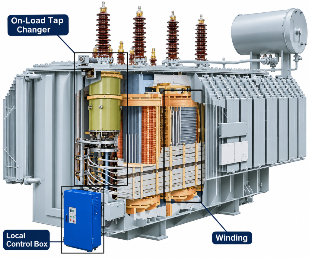
An On-Load Tap Changer is a mechanical switching device installed in a power transformer to adjust its turns ratio while the transformer is energized and carrying load current.
By changing the effective number of winding turns, the OLTC regulates the transformer’s output voltage according to grid requirements.
For example, a 110/10kV or 110/35kV transformer may experience changes in output voltage due to variations in transmission voltage and load demand. The OLTC adjusts the transformer ratio to compensate for these variations.
The main functions of an OLTC include:
-
Maintaining secondary voltage within the required operating range.
-
Compensating for changes in grid voltage.
-
Supporting voltage regulation under varying load conditions.
-
Improving power supply stability.
-
Reducing the need for power interruption during voltage adjustment.
Unlike an Off-Circuit Tap Changer, an OLTC can perform tap-changing operations without disconnecting the transformer from the power supply.
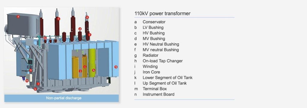
2. Working Principle of an OLTC for 110kV Transformers
The OLTC operates by changing the connection point of the transformer winding to adjust the effective turns ratio.
A typical OLTC system consists of several important components:
></table class=”table table-hover table-bordered text-center”>>
| Component | Main Function |
|---|---|
| Tap Selector | Selects the required winding tap position |
| Diverter Switch | Transfers current from one tap to another |
| Transition Resistor or Reactor | Limits circulating current during switching |
| Operating Mechanism | Drives the tap-changing operation |
| Motor Drive Unit | Provides electrical operation |
| Position Indicator | Displays the current tap position |
| Automatic Voltage Regulator (AVR) | Controls voltage regulation |
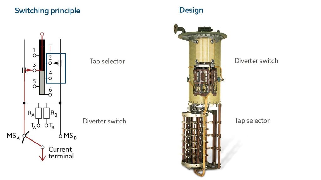
How Does the OLTC Change Taps?
A typical resistive OLTC follows a switching sequence:
-
The tap selector prepares the next tap position.
-
The diverter switch begins transferring the load current.
-
Transition resistors temporarily limit circulating current between adjacent taps.
-
The current transfers to the new tap position.
-
The transition resistors are disconnected from the normal current path.
This process allows the transformer to change its voltage ratio without interrupting the load supply or directly short-circuiting adjacent winding taps.
The actual switching sequence depends on the OLTC design and manufacturer.
3. Common OLTC Tap Ranges for 110kV Power Transformers
The tap range determines how much the transformer voltage ratio can be adjusted.
For 110kV power transformers, common engineering configurations include ±8 × 1.25%, ±10 × 1.25%, and ±12 × 1.25%.
></table class=”table table-hover table-bordered text-center”>>
| Tap Configuration | Total Tap Range | Number of Positions |
|---|---|---|
| ±8 × 1.25% | ±10% | 17 |
| ±10 × 1.25% | ±12.5% | 21 |
| ±12 × 1.25% | ±15% | 25 |
These are representative design options rather than mandatory configurations for every 110kV transformer.
Example: 110/10kV Power Transformer
Consider a transformer with the following rated parameters:
></table class=”table table-hover table-bordered text-center”>>
| Parameter | Specification |
|---|---|
| Rated Voltage | 110/10kV |
| Rated Capacity | 31.5MVA |
| Tap Changer Type | OLTC |
| Tap Range | ±8 × 1.25% |
| Number of Positions | 17 |
| Voltage Regulation | High-Voltage Winding |
The actual winding connection, tap winding arrangement, and OLTC installation position must be confirmed through the transformer design.
For example, if the 110kV winding is the regulating winding, its effective turns can be adjusted to compensate for changes in the grid voltage and maintain the required secondary voltage.
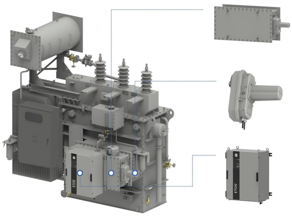
4. How to Select an OLTC for a 110kV Power Transformer?
Selecting an OLTC requires coordination between the transformer electrical design and the tap changer manufacturer’s technical specifications.
The following parameters should be carefully evaluated.
4.1 Rated Through-Current
Rated through-current is the current that the OLTC can continuously carry under specified operating conditions.
It must be compatible with the current flowing through the regulating winding.
The required current depends on transformer capacity, winding voltage, winding connection, and tap winding arrangement.
For example, the rated current of a 31.5MVA transformer cannot be used directly as the OLTC rated through-current without considering the actual regulating winding configuration.
4.2 Step Voltage
Step voltage refers to the voltage difference between two adjacent tap positions.
It is determined by the voltage contribution of the regulating winding section.
The OLTC must be capable of switching the specified step voltage under its rated operating conditions.
4.3 Tap Range and Number of Positions
The required tap range depends on the grid voltage regulation requirements.
A wider tap range provides greater adjustment flexibility but also affects winding design, insulation coordination, and OLTC selection.
4.4 Switching Capacity
Switching capacity is an important OLTC selection parameter.
The diverter switch must safely transfer current between adjacent tap positions under specified electrical and operating conditions.
The rated switching capability must be compatible with the transformer’s maximum step voltage and through-current.
4.5 Insulation Level
For 110kV transformers, insulation coordination is especially important.
The OLTC insulation requirements depend on its installation position, connection arrangement, winding insulation design, and electrical stresses.
The supplier should provide relevant dielectric test information and insulation specifications.
4.6 Operating Mechanism
Most modern OLTC systems use motor-driven operating mechanisms.
Important considerations include:
-
Motor drive voltage.
-
Operating speed.
-
Tap position indication.
-
Mechanical and electrical interlocking.
-
Remote control capability.
-
Manual emergency operation.
-
Limit switches and position feedback.
A suitable operating mechanism should support reliable local and remote operation.
5. OLTC Installation Position in 110kV Power Transformers
The installation position of an OLTC depends on the transformer winding configuration and electrical design.
For many 110kV power transformers, the OLTC is installed on the high-voltage winding, frequently at the neutral end when the winding arrangement and insulation design permit.
Common considerations include:
High-Voltage Winding Regulation
The OLTC changes the effective turns of the high-voltage winding to regulate the transformer voltage ratio.
Neutral-End Installation
For suitable star-connected windings, locating the regulating section near the neutral point can reduce the insulation requirements compared with installation at the line end.
Separate OLTC Compartment
Many oil-immersed OLTC designs use a separate oil compartment for the diverter switch to prevent switching-related contamination from entering the main transformer oil system.
The final installation arrangement must be determined by the transformer manufacturer and OLTC supplier.
6. OLTC Operation and Automatic Voltage Regulation
An OLTC can operate through local manual control, remote electrical control, or automatic voltage regulation.
Manual Operation
Operators can initiate tap changes through the local operating mechanism or control panel.
Manual operation is commonly used during commissioning, maintenance, and special operating conditions.
Remote Electrical Operation
The OLTC can receive operating commands from a remote control system, such as a substation control room or SCADA system.
This allows operators to adjust transformer voltage without accessing the transformer installation area.
Automatic Voltage Regulation
An Automatic Voltage Regulator (AVR) monitors transformer voltage and sends control signals to the OLTC when the measured voltage deviates from the configured setpoint.
A typical automatic regulation process includes:
-
Measuring the transformer secondary voltage.
-
Comparing the measured value with the reference voltage.
-
Evaluating the voltage deviation.
-
Applying a time delay to prevent unnecessary switching.
-
Sending a tap-changing command when required.
-
Verifying the new tap position.
Automatic voltage regulation helps maintain stable output voltage under changing grid and load conditions.
7. OLTC Maintenance and Common Faults
Regular OLTC maintenance is essential for maintaining switching reliability and extending equipment service life.
Because the diverter switch operates mechanically and electrically, its contacts, insulation oil, and drive mechanism require periodic inspection.
Common OLTC Faults and Inspection Methods
></table class=”table table-hover table-bordered text-center”>>
| Common Problem | Possible Cause | Recommended Inspection |
|---|---|---|
| Abnormal switching noise | Mechanical wear or loose components | Mechanical inspection |
| Tap position error | Position feedback or control circuit fault | Control system verification |
| Oil contamination | Switching contact wear | OLTC oil testing |
| Switching failure | Motor drive or mechanism fault | Drive mechanism inspection |
| Contact overheating | Contact wear or poor connection | Contact resistance measurement |
| Oil leakage | Seal aging or damaged joints | Sealing inspection |
OLTC Oil Inspection
In OLTC designs with a separate diverter-switch oil compartment, switching operations can produce electrical decomposition products and carbon particles.
Oil condition should be monitored according to the OLTC manufacturer’s maintenance recommendations.
Relevant tests may include:
-
Oil dielectric breakdown voltage.
-
Moisture content.
-
Dissolved gas analysis, where applicable.
-
Visual inspection for carbon contamination.
-
Oil leakage inspection.
OLTC oil testing should be evaluated separately from the main transformer oil system when separate compartments are used.
Mechanical Inspection
Mechanical maintenance should focus on:
-
Diverter switch contacts.
-
Tap selector contacts.
-
Drive motor and gearbox.
-
Operating mechanism.
-
Position indicators.
-
Mechanical interlocks.
-
Limit switches.
Maintenance intervals should follow the manufacturer’s instructions, switching operation count, operating conditions, and condition-monitoring results.
8. OLTC vs Off-Circuit Tap Changer for 110kV Transformers
Although both OLTC and Off-Circuit Tap Changers adjust the transformer turns ratio, their operating conditions and applications are different.
></table class=”table table-hover table-bordered text-center”>>
| Comparison | OLTC | Off-Circuit Tap Changer |
|---|---|---|
| Full Name | On-Load Tap Changer | Off-Circuit Tap Changer |
| Transformer Energized | Yes | No |
| Load Interruption | Not required for tap changing | Required |
| Operating Method | Motor-driven or manual | Usually manual |
| Mechanical Complexity | Higher | Lower |
| Maintenance Requirements | More extensive | Generally simpler |
| Typical Application | Grid and large industrial transformers | Transformers with infrequent adjustment needs |
For 110kV utility transformers requiring continuous voltage regulation, OLTC is commonly preferred.
For applications where voltage adjustment is infrequent and the transformer can be de-energized before switching, an Off-Circuit Tap Changer may be suitable.
The final choice should follow the grid operator’s requirements and transformer operating conditions.
9. International Standards for 110kV Transformer OLTCs
When purchasing an OLTC for a 110kV power transformer, compliance with relevant international standards is an important consideration.
IEC 60214-1: Tap-changers – Performance requirements and test methods
This standard specifies performance requirements and test methods for tap changers.
IEC 60214-2: Tap-changers – Application guidelines
This document provides application guidance for selecting and applying tap changers.
IEC 60076 Series: Power Transformers
The IEC 60076 series covers general requirements, temperature rise, insulation, and testing of power transformers.
Buyers should confirm the applicable standard editions and project-specific requirements with the transformer and OLTC manufacturers.
10. What Information Is Required When Purchasing an OLTC for a 110kV Transformer?
For transformer manufacturers and procurement engineers, providing complete technical information helps ensure accurate OLTC selection and quotation.
></table class=”table table-hover table-bordered text-center”>>
| Required Parameter | Example / Description |
|---|---|
| Transformer Rated Voltage | 110/10kV, 110/20kV, 110/35kV |
| Transformer Capacity | 31.5MVA, 40MVA, 50MVA, 63MVA |
| Tap Changer Type | OLTC |
| Regulating Winding | High-voltage / other specified winding |
| Rated Through-Current | According to winding design |
| Step Voltage | According to tap winding design |
| Tap Range | ±8 × 1.25%, etc. |
| Number of Positions | 17, 21, 25, etc. |
| Operating Mechanism | Motor-driven |
| Control Mode | Local / Remote / Automatic |
| Insulation Requirements | According to installation position |
| Applicable Standard | IEC 60214 |
In addition, the transformer manufacturer should provide the winding connection diagram, tap winding arrangement, and relevant insulation information to the OLTC supplier.
This information is essential for verifying compatibility between the tap changer and transformer design.
11. Conclusion: Reliable OLTC Selection for 110kV Power Transformers
An On-Load Tap Changer is an important component of many 110kV power transformers, enabling voltage regulation without interrupting power supply.
Selecting the correct OLTC requires careful evaluation of rated through-current, step voltage, tap range, switching capacity, insulation level, and operating mechanism.
Proper installation, automatic voltage regulation, and regular maintenance are also essential for ensuring reliable transformer operation.
For transformer manufacturers and EPC contractors, working with experienced OLTC suppliers and coordinating technical requirements during the transformer design stage can help reduce compatibility risks and improve long-term operating reliability.
ZTELEC YUGUANG manufactures customized 110kV power transformers and provides engineering coordination for transformer accessories, including OLTC configuration according to project requirements.
Whether your project involves a 110/10kV distribution substation, a 110/35kV industrial transformer, or a renewable energy grid connection, proper OLTC selection is essential to achieving reliable voltage regulation.
Contact ZTELEC YUGUANG for 110kV power transformer technical specifications, customized design solutions, and project quotations.
You may also find these interesting: